

CP Tutorial
What is Corrosion?
What is Cathodic Protection?
Corrosion is defined in Webster's dictionary as "…the action or process of corrosive chemical change…a gradual wearing away or alteration by a chemical or electrochemical, essentially oxidizing process."
In the performance of our daily work and job responsibilities we usually relate corrosion to the rusting and wasting away of a pipe which is buried in the ground. In this sense, corrosion can be considered as a process of natural forces working to restore the refined works of man to their original state of complete and uniform equilibrium. Thus, in the case of the buried pipe, corrosion is the process of natural forces working to restore the iron in the steel pipe, through rusting, to its original stable form of iron oxide, or native iron ore.
The type of corrosion with which we are most familiar, and the type which causes extensive damage to buried pipe, is electrochemical corrosion. This form is also widely known as galvanic corrosion, and is sometimes loosely referred to as electrolysis.
 1: Electrochemical Corrosion |
| There are several other types of corrosion which are also important to consider. |
Electrochemical Corrosion (fig. 1) takes place when two different metals come into contact with a conductive liquid -- usually impure water or soil moisture -- resulting in a flow of direct current electricity. The current always flows away from the anodic metal (anode), and the anode is corroded. The current flows through the electrolyte to the cathodic metal (cathode), but the cathode is not corroded. The potential that causes the current to flow is always due to some kind of difference between the anode and the cathode, such as a difference in the two metals, concentration of the conductive liquid, a difference in temperatures, a difference in the amount of oxygen present, or some other difference in conditions.
Technically, four conditions must always be present to create a galvanic cell and for corrosion to occur. There must be two different metals, one acting as the anode, and the other acting as the cathode. There must be an electrolyte to provide a path for current to flow from the one metal to the other. And there must be a direct electrical contact between the two metals to complete the electrical circuit. The flow of current through the electrolyte is always from the anode to the cathode. Wherever electrical current leaves the anode to enter the electrolyte, small particles of iron are dissolved into solution, causing pitting at the anode. Wherever the current enters the cathode, molecular hydrogen gas is formed on the surface and the cathode is preserved and protected from corrosion.
If one of the four conditions of a galvanic cell is removed, corrosion cannot continue. It is the removal of one of the four conditions, to reduce or interrupt the flow of galvanic current, which is the basis for cathodic protection and all other forms of corrosion control.
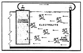 2: Simple Flashlight Battery |
Probably one of the most common galvanic cells that we can consider as an example is the simple flashlight battery (fig. 2). The metal, zinc, is used as the case of the battery and is the anode. The carbon rod in the center of the battery is the cathode. And the space in between the two is filled with an acid (or alkaline) substance, which is the current conducting material, the electrolyte. Three of the four conditions of a galvanic cell are present, so there is yet no reaction.
But when the battery is connected to an external circuit, and electric current is then caused to flow from the zinc (anode), through the electrolyte to the carbon rod (cathode). Oxygen is evolved at the face of the anode, particles of zinc are dissolved into the solution, and hydrogen gas is deposited on the carbon rod. If the flow of current is not stopped, the zinc case will corrode to penetration, and the electrolyte will leak from the battery case.
 3: Pipe/Pipeline 4: Mill Scale 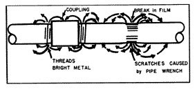 5: Tool Marks 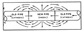 6: New Pipe 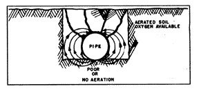 7: Excavated Ditch 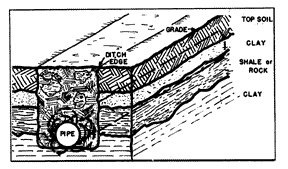 8: Varying Soils 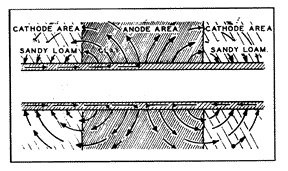 9: Changing Conditions 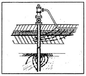 10: Vertical Structure |
The formulation of oxygen at the anode, and hydrogen at the cathode -- on the surfaces of the two different metals -- may bring about a condition known as polarization. Such polarization will increase the resistance to the flow of electricity and will therefore reduce the rate of corrosion. This is also illustrated in the use of the flashlight battery. When the battery has been given a rest after moderate use, and the gasses have dissipated, the battery will function again with renewed life.
The numerous galvanic cells which cause corrosion on buried pipe all work very much in the same manner as the simple battery cell. The actual mechanisms of the corrosion process, as discussed and illustrated earlier, may be more complex, but the principles are the same.
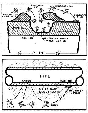
When a piece of pipe or a thousand-mile-long pipeline (fig. 3) is buried in the ground, the moisture in the soil is always the electrolyte. The anode and the cathode areas are both on the same pipe structure, and the pipe itself provides the return circuit.
The lower the resistance, or the more conductive the electrolyte, the greater will be the flow of electricity, and the more active the rate of corrosion. Thus, the rate of corrosion in salt polluted soils and in clay gumbo soils will be much greater than if the same pipe were backfilled with high resistant sand or gravel. If the sand or gravel backfill could be made to be and remain "bone-dry," then we would have eliminated the electrolyte entirely and the process of galvanic corrosion could not continue.
Different corrosion cells can occur within the same inch on the same joint of pipe, or they could even be miles apart on a well-coated pipeline. Some of the corrosion cells on a pipe may be caused by the various elements of iron, manganese, carbon and trace elements which all occur within the typical composition of carbon steel.
Some cells can be created by the different iron compounds found in mill scale (fig. 4), or in atmospheric rust.
Tool marks (fig. 5), scratches, new surfaces exposed by pipe threads are almost always anodic to other pipe surfaces and are subject to active corrosion.
When a piece of pipe is removed from an existing pipeline and replaced with a piece of new pipe (fig. 6), or with a tee, or with some other new structure, the new material is almost always anodic to the old material. The old material is not necessarily made of any better quality material to resist corrosion, except that it is already polarized and protected by various protective films created by the prior action of the electrolytic process.
The various physical conditions of the soil environment in themselves create different types of corrosion cells. These are sometimes called "concentration cells."
One such concentration cell is created when the pipe is installed along the bottom of the excavated ditch (fig. 7) on dense and undisturbed soil, while the rest of the pipe wall is in contact with the mixed, loose and aerated soil of the backfill. This soil condition will also hold more moisture at the bottom of the pipe, and the combination of these favorable conditions makes the bottom anodic with respect to the other parts of the circumference of the pipe. A row of pits along the bottom of the pipe is the common result.
Concentration cells of a different type are established when the pipe ditch is made through areas where there are layers of widely different kinds of soil (fig. 8), such as layers of top soil, clay and rock. Wherever clods of clay come into contact with the steel, these points would be anodic with respect to other parts of the pipe which are in contact with the higher resistant soil and rock.
Most concentration cells occur in the soil where conditions change (fig. 9), for example, from relatively higher resistant loam to lower resistant clay soils, or alkaline areas. These corrosive areas are commonly referred to as "hot spots."
These same concentration cells are also present when a structure is installed vertically (fig. 10) through various earth strata. These can be found on well casings, foundation piling, or even on steel fence posts.
When a pipe is first backfilled, many corrosion cells are quickly set up due to a combination of causes as already discussed. In every case, corrosion is taking place at the anodic areas -- iron is being dissolved -- and hydrogen is being plated out of the electrolyte onto the face of the cathodic areas of the pipe. There are some very weak corrosion cells, and on the opposite hand there are some very strong cells. As these processes of corrosion and polarization continue, some of the weaker cells become completely polarized, and the anodes of these cells become cathode to larger cells. The net result is that the same total amount of current continues to flow from fewer anodes, causing failure to the pipe at a faster rate.
The rate at which galvanic corrosion takes place is governed basically by the chemical components which comprise the corrosion cell. Every metallic element or alloy possesses, or generates its own specific solution potential when buried in the ground. That is, there is a difference in electrical pressure (voltage) between the metal and the soil. This can be measured very precisely by attaching the negative lead of a voltmeter to the buried metal, and the positive lead of the voltmeter to a copper sulphate electrode placed in contact with the soil.
When a piece of steel pipe is buried in the ground, the solution potential of the steel (essentially iron) can be observed to be approximately one-half volt. When a piece of galvanized steel pipe (zinc surface) is buried, the solution potential will be observed to be over one volt. Then, if the potential is measured directly between the steel and the galvanized pipe, we will observe a potential of approximately one-half volt, which is the arithmetical difference between the two separate solution potentials. By bonding (connecting) the two pipes together with a wire, we have established a galvanic cell, with the galvanized pipe being anodic to the steel pipe. Current is caused to flow from the galvanized pipe through the soil to the steel pipe. The zinc is being corroded, and the steel pipe is being polarized and protected from corrosion.
The relative solution potentials of a number of metals, as observed in sea water, are shown in the following list.
| Lithium +2.96 Volts Rubidium +2.93 Volts Potassium +2.92 Volts Strontium +2.92 Volts Barium +2.90 Volts Calcium +2.87 Volts Sodium +2.71 Volts Magnesium +2.40 Volts Aluminum +1.70 Volts Zinc +0.76 Volts Chromium +0.56 Volts | Nickel +0.23 Volts Tin +0.14 Volts Lead +0.12 Volts Iron +0.04 Volts Hydrogen 0.00 Volts Copper (Cuprous) -0.80 Volts Silver -0.80 Volts Mercury -0.80 Volts Platinum -0.86 Volts Gold -1.50 Volts |
These are relative values only, compared to hydrogen, and the specific voltages will vary under the different conditions of different electrolytes, different temperatures, concentration, etc. Any group of metals such as this, arranged in order of the magnitude of their solution potentials, is commonly called by several names, a galvanic cell, or and electrochemical series. If any two metals are selected, joined together electrically and buried underground, they will establish a galvanic cell. The metal that is higher in the list, the one having the higher solution potential, will be anodic to the other. The anodic metal will corrode, and the metal that is cathodic will be protected from corrosion.
This is the basis in principle of cathodic protection. Cathodic Protection can be defined as…the control of electrolytic corrosion…by the application of direct current in such a way that the structure to be protected is made to act as the cathode of an electrolyte cell.
The greater the separation of the two metals in the series, the more rapidly will the galvanic corrosion proceed. While those metals shown higher in the list will create higher potentials, they are relatively unstable and expensive to produce in commercial quantity. As we come down in the list, magnesium is the first metal which is economical to produce in commercial volume. It is for these reasons: that magnesium is relatively high in the galvanic series, and relatively low in cost, that it is used in the manufacture of sacrificial soil anodes for the cathodic protection of steel pipe buried in the ground.
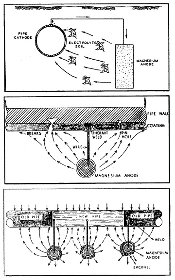 11: Magnesium Anode |
When a sacrificial magnesium anode (fig. 11) is buried in the ground and is connected to a steel pipeline through a copper wire, a strong galvanic cell is established (in the soil electrolyte) having a potential of approximately 1.5 volts. The potential thus created by the formation of this galvanic cell is then usually sufficient to overcome all other naturally existing galvanic cells on the pipeline in the immediate vicinity of the anode. That is to say, all of the anodes of the small naturally existing cells on the pipe have been made to be cathodes to the new magnesium anode which has been attached to the pipe. The magnesium anode will corrode instead of the pipe; the magnesium alloy metal will be sacrificed to save the steel pipe. This is the purpose and the effect of cathodic protection.
While magnesium anodes can be beneficial in slowing the rate of corrosion on a buried pipeline under ideal conditions, they do have their effective limitations.
The driving potential of sacrificial anodes are completely limited to the difference in potential between the anode and the cathodes. As has already been illustrated, the maximum potential that might be obtained between magnesium anodes and steel pipe is slightly more than 1.5 volts. However, to overcome the stronger potentials of external interference as one example. Such interference often is produced as a result of the operation of a cathodic rectifier on a foreign structure in close proximity to the pipeline receiving the interference. Such interference could also come from DC electric railroads or some other source of stray DC current in the soil. But DC interference problems are usually corrected by mutual cooperation and compensation between the two structure owners, which procedures are too involved for explanation within this discussion.
The current output of a single galvanic anode is quite limited and can be affected by any one, or even all of the following conditions:
- The amount of bare steel to be protected, as related to the effectiveness of the coating on the pipe (if any).
- The resistivity (conductivity) of the soil electrolyte environment between the anode and the pipe structure.
- The size and physical shape of the anode.
- The metallurgical composition of the anode.
- The kind and amount of backfill material around the anode and the pipe.
- The physical distance between the anode and the pipe structure.
- The depth at which the anode is buried.
- The number of anodes attached to the pipe, and their spacing.
- The pipe-to-soil potential of the pipe structure.
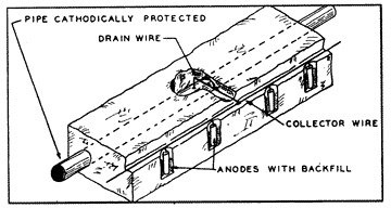
While a single sacrificial anode could provide adequate cathodic protection to miles of a very well coated pipeline with few breaks in the coating, it can afford adequate cathodic protection to only a relatively few feet of large diameter uncoated pipe under severely corrosive conditions. Under these severe conditions it would be necessary to install many anodes (fig. 12) at very close intervals in order to provide sufficient potential to all surface areas of the pipe.
 12: Many Anodes 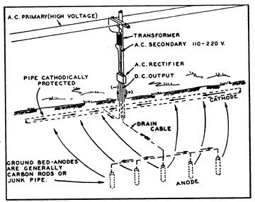 13: Cathodic Rectifier/Impressed Current Groundbed System |
A more effective and positive method of cathodic protection is through the installation of a cathodic rectifier and impressed current groundbed system (fig. 13) instead of with multiple magnesium anodes. By this method an electrolytic cell is developed artificially, where the entire structure to be protected is made to be the cathode of the cell, and the installed groundbed is the anode. The current is made to flow from the groundbed to the structure by converting alternating current power to direct current and impressing the direct current into the earth through the groundbed.
A cathodic groundbed consists of a designed number of carbon, graphite, cast iron or junk steel anodes buried in the ground at various depths and configurations. Commonly, the groundbed will consist of approximately 20 cast iron anodes, installed in augered holes 15 feet apart, and backfilled with carbon dust to lower the anode-to-earth resistance. These anodes will all be connected together in parallel, with the header cable attached to the positive terminal of the rectifier.
The rectifier instrument consists of two basic devices: a transformer to convert purchased AC power from 115, 230 or other supply voltage, to the much lower DC voltage needed for cathodic protection; and the rectifying device to convert the low voltage AC to DC. A second cable is attached to the buried pipeline and connected to the negative terminal of the rectifier instrument to complete the return circuit.
Voltage adjusting linkage is provided on the rectifier so that the DC current output can be adjusted to any value as may be required to provide an adequate protective potential on the pipe structure. When the AC supply is turned on to the rectifier, the transformer reduces the AC voltage to the desired level, converting it to direct current through the rectifying stacks and is impressed into the earth through the groundbed. As with other galvanic cells, the impressed current collects on the bare steel surfaces, or at the voids in the coating, and the pipe is used as a return to the negative terminal of the rectifier to complete the circuit.
The rectifier-groundbed system has many advantages in the application of cathodic protection to a buried or submerged structure:
- It allows for any reasonable driving voltage that may be desired for effective control of corrosion.
- It allows for any reasonable current output that may be desired for effective control of corrosion.
- It can be used with almost any resistivity soil environment.
- The system can be used on bare or coated pipeline systems.
- Structures of any size can be made to be cathodic and be protected.
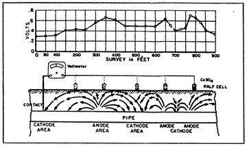 14: Pipe-to-Soil Potential |
The pipe-to-soil potential test (fig. 14) has been established by corrosion engineers as a standard measurement technique in the evaluation of corrosion control and the degree of cathodic protection applied to buried metallic structures. The copper sulphate half cell reference electrode is most commonly used to contact the soil. Normally, the natural static potentials of unprotected buried steel will vary from -0.30 to -0.80 volts, with reference to the copper sulphate electrode. Such differences in the pipe-to-soil potentials observed at various intervals along a pipeline indicate the voltage drops in the soil between the test points. This means that galvanic currents will flow through the soil between the anodic and the cathodic points, the magnitude of current flow depending on the resistivity of the soil (electrolyte) and the voltage drop in the galvanic cells.
If the static pipe-to-soil potentials along a pipeline were of equal values, galvanic currents could not flow, and there would be no corrosion.
When enough external counter-current is provided to a corroding section of a pipeline to exactly cancel out the galvanic currents, the pipe-to-soil potentials at the anodic points will be equal to the pipe-to-soil potentials of the cathodic points, and the voltage drop between the points would be zero. That point of theoretical potential equalization is usually at or near the open circuit potential of the anodic point.
For example, if the open circuit pipe-to-soil potential of an anodic point is -0.65 volt, then corrosion will be stopped if the potential of the cathodic point(s) is made more negative and equal to this value. This is a basic criterion for the cathodic protection of a buried structure. However, it would be impractical and almost impossible to determine the open circuit potential values and points of potential equalization along a pipeline, so corrosion engineers have established a second and more practical criterion for adequate cathodic protection.
It is generally accepted by the corrosion engineers that a structure will be under complete cathodic protection if the pipe-to-soil potential at all points on that structure is maintained at a minimum level of -0.85 volt. This value represents over-protection in most instances, since the points of potential equalization, as pointed out above, is usually less negative than -0.80 volt. This is the most practical and economical criterion to consider in testing for the existence of corrosion on any buried and coated pipeline.
Structure-to-soil potentials should be observed using a potentiometer, which draws no current, or a high resistance voltmeter, which draws only a very small current. A copper-copper sulphate electrode is used for the reference contact with the electrolyte (soil), and there must be direct contact with the structure (pipe).
To make a pipe-to-soil test observation, the lead wire attached to the copper sulphate electrode is attached to the positive (+) post of the meter. A wire attached to the negative (-) post of the meter is attached solidly to the pipe at any convenient point. This contact can be made by clipping directly to an above-ground valve, fitting, riser, or even by attaching to a probe bar pushed into the ground to contact the pipe.
The plug end of the copper sulphate electrode is then placed firmly against the moist soil at a position relative to the top of the buried pipe. If the soil is dry, it will be necessary to spill just a little water onto the ground (1/2 cupful) in order to ensure good contact between the soil and the electrode. The pointer on the voltmeter will then indicate the pipe-to-soil potential at that particular point on the pipeline.
Continuing and using the same direct contact to the pipe, but then using a very long wire between the meter and the copper sulphate electrode, it will be possible to move the electrode about and take many pipe-to-soil test observations at any number of intervals for hundreds of feet along the length of a pipeline.
If all test observations over the entire structure are found to be -0.85 volt or greater, it can be concluded that the entire structure is cathodic with respect to the sacrificial anodes (or with respect to the rectifier groundbed) and that there is no active corrosion taking place. This value of -0.85 volt considers a "built-in" constant of -0.52 volt as the solution potential between copper and copper sulphate in the reference electrode.
Pipe-to-soil observations should be made whenever there is any question or any doubt that the structure may not be under full cathodic protection. It is desirable to practice the re-observation of pipe-to-soil potentials at regular, say, six-month intervals to have assurance that no physical changes had previously been made that would upset the balance of the cathodic protection circuit. This is for confirmation purposes, and to discover any changed condition which could result in corrosion damage to the structure. The period of retesting pipe-to-soil potentials should never exceed one year.
Whenever any work is performed directly on the structure which may affect the cathodic protection balance, it would then be prudent to retest the pipe-to-soil potential at the completion of that work. Such work would include any activity which might affect the insulation or the shorting of any portion of the structure to another structure, any work on or addition to insulating fittings, any addition or removal of pipe to the length of the system, any pollution of the soil which my lower the resistivity of the soil environment, any indirect contact to the structure by a different metallic structure, any nearby construction and subsequent operation of a cathodic rectifier by others, any other new source of stray DC into the earth, etc. Any changes which do occur to reduce the pipe-to-soil potential on the structure under cathodic protection below a level of -0.85 volt should be removed or corrected to restore the structure to a protective level.
It should be remembered that cathodic protection is only one tool used in an overall program of corrosion control, and is often used to supplement other efforts to arrest and control the process of corrosion. Some of the other methods used in corrosion control are:
- Insulating the internal or external surfaces of a structure from the electrolyte by the installation of paint, wax, coal, tar, asphalt, plastic tape, epoxy resin, or other coating or lining material.
- Installing the structure in a high resistant or well-drained environment, such as in or on sand, crushed rock, etc.
- Cladding, lining, dipping, electroplating, or metalizing to coat a metallic surface with a metal, alloy, or material of superior resistance.
- The addition of selected chemical inhibitors, passivators, or dessicants.
- The removal of oxygen, carbon dioxide, or other gasses from, or the addition of inert gasses, such as nitrogen, to the environment.
- The careful consideration and selection off metals, alloys, plastics, ceramics, or other materials, to be used in conjunction with a necessary metal.
- Control of the environment to lower temperatures.
- The reduction of velocities and/or throughput at the face of the corroding material.
- The installation of in-line insulating materials.